Ceramics for Hall Effect Thrusters
They now form a significant section of the electric propulsion market but are by no means the only option; Gridded Ion Thrusters, Field Emission Electric Propulsion ( FEEP), Pulsed Plasma Thrusters (PPT) and a host of other specialist thrusters that operate with propellants as diverse as PTFE, caesium, indium and mercury are now common. They all operate in different ways but without using the channel design of a Hall Effect Thruster.
Thruster selection depends on the size of the satellite, the number of thrusters, the use of the thruster, station keeping, altitude positioning and pulsed or constant acceleration for exploration.
Hall Effect Thrusters use inert gases as the propellant, typically but not exclusively xenon. This removes both the possibility of accidental flammable explosion and reduces the initial launch weight of the satellite.
The electrical power of the satellite is developed from solar arrays. This electrical energy is then used to power the satellite systems and provide energy to ionise the propellant and also accelerate the ions by creating an electrical potential sufficient to achieve propellant speeds of 10 to 50 kilometres a second. The propellant speed sounds impressive but this will only generate between 40 and 600 millinewtons of force. On a standard system, that is like the weight of a small coin applying force to the satellite.
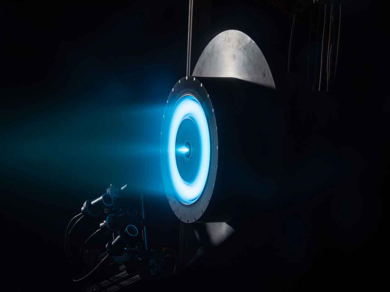
The effectiveness of a Hall Effect Thruster depends on many factors but one of the key components is the ceramic channel. This not only insulates between the anode and cathode and not only requires the best electrical insulation possible but also must have a low density for reducing weight leaving the earth’s atmosphere. The material must also be able to withstand the impact of these energised ions or plasma on the surface.
The impact of these charged ions on the surface of the ceramics can cause secondary electron emissions (SEE) where the energy of the charged particles impacting the surface transferers to the surface of the ceramic and can be sufficient to eject electrons for the material creating erosion.
The life of a satellite held in orbit can be constrained by the amount of propellant, the lifetime of the ceramic and the lifetime of the technology the satellite supports. The rapid development of technology may even make these systems redundant while they still have the capability to function.
The propellant options are expanding; xenon, Iodine, argon and krypton are available but xenon is the most commonly used.
Ceramic Channels
Low in density, these materials also have to be mechanically strong enough to survive the atmospheric launch and be resistant enough to the bombardment of ions so that the erosion of the channel doesn’t become the constraining factor in the life of the satellite.
Many Grades of boron nitride and BN composites have been used and evaluated and it is difficult to specify a grade of material as being the correct grade for all applications as there are many factors that have a bearing on the material selected.
Consistency
Material selection is also dependant on other factors including the size of the channel required, the features required in the channel, cost, availability and possibly the location of the manufacturer.
Channel Size
Please discuss your exact requirements with us. We can also cover discussions under NDA arrangements.
Features
Cost
The life of a thruster is a closely guarded commercial secret as knowing the life of a channel can lead to the satellite life and give a commercial advantage. Hence little more than general information is available in the public domain.
Electrical insulation can also be required in other Hall Effect satellite systems with high purity alumina as the material of choice.